Series 431 GR2270 ‘Z’ Axis Camtrac Dual Well Mechanical Test Kits
Technical Specifications
- Hinged 3/8″ thick G10 Probe plate
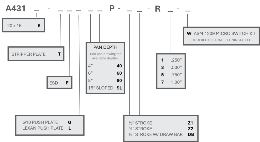
- Optional 3/8″ thick G10 or 1/2″ thick clear Polycarbonate Push Plate
- Optional 1/2″ or 3/4″ Stroke. (Draw bar version only available in 1/2″ stroke)
- Locking bars to prevent opening the top cam assembly during test.
- 12 Position Interface that accepts Industry Standard GR2270 style (VG) blocks
- Five Piece Sheet Metal Enclosure for ease of modification to add connectors, fans, and other components.
- Tooling Holes provided for accurate drilling of plates
- Optional Sheet Metal pan depths
- Optional ESD plates. (-E)
- Optional Stripper plate (-T)
How To Determine Kit Dimensions
First Dimension: Left To Right
Second Dimension: Front To Back
Example: A4316 GR-CT103S-DW 20″ x 16″
20 ” Left to Right
16″ Front to Back
How To Determine UUT And Pan Measurements
| Kit Size | Max UUT Size Per Well |
Max UUT Size Per Well, with Stripper Plate |
| GR-CT103S-DW: 20 x 16 (A4316) | 5.00 x 8.00 | 5.00 x 7.50 |
| All dimensions in inches |
Parts Generator


