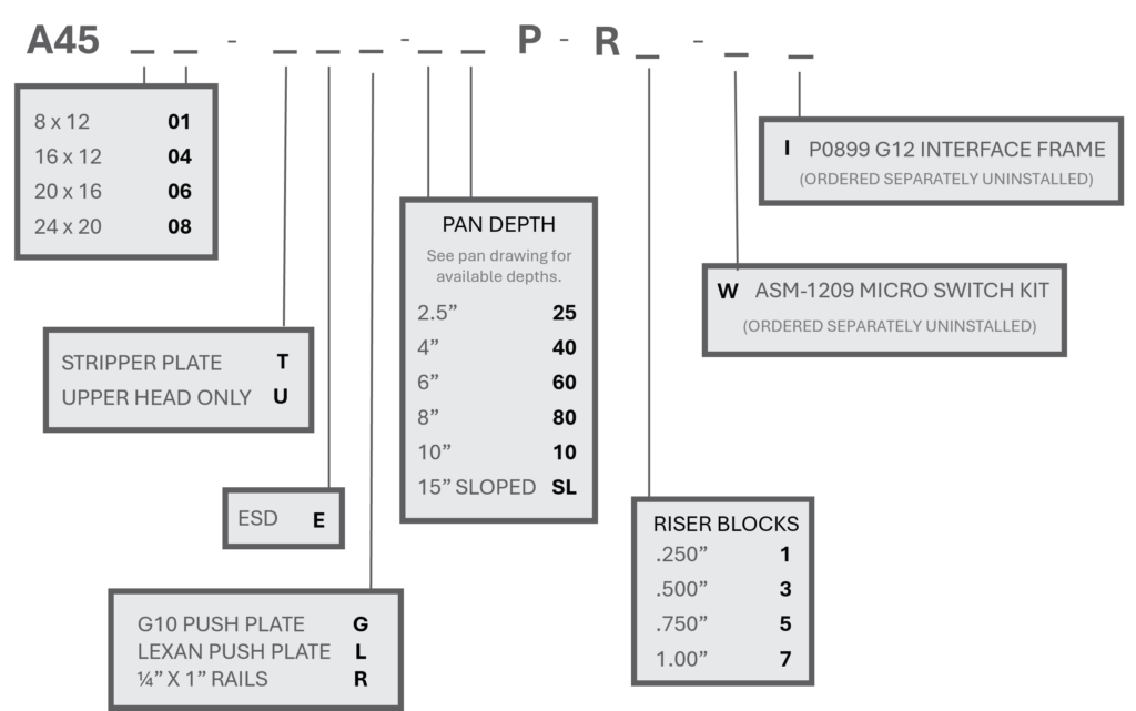
Series 45 CamGate ‘Z’ Axis Test Kits.
The CG Series 45 CAM/GATE linear over clamp kits utilize the same patented “Z” axis motion as our CAM/TRAC® Series products offering precise Z axis linear motion when testing higher point count and finer pitch test centers. By using the Z axis motion, side load of the test probes is minimized thus increasing probe life and performance. The latch assembly engages and disengages when actuating the clamping assembly. The CAM/GATE utilizes a cam roller system for precision guiding and smooth operation and 1.00” push plate movement. The gate assembly is movable to three different positions which allows for the versatility of top side probing, or relocating the frame assembly for PCA’s the have tall components
Technical Specifications
- Hinged 3/8″ thick G10 Probe plate
- Optional 3/8″ thick G10 or 1/2″ thick clear Polycarbonate Push Plate
- Optional 1/4″ X 1″ Aluminum Rails (-R) for PCB access
- 1″ stroke
- Five Piece Sheet Metal Enclosure for ease of modification to add connectors, fans, and other components.
- Optional Sheet Metal pan depths
- Tooling Holes provided for accurate drilling of plates
- Guide pins for accuracy on floating push plates. (-G and -L )
- Optional ESD plates. (-E)
- Optional Stripper plate (-T)
- The Push Frame is adjustable. Lower position, (standard for -G) for top side probing with a G10 push plate. Middle Position (standard for -L), Top position for use with assemblies requiring clearance for PCA’s with tall components.
How To Determine Kit Dimensions
First Dimension: Left To Right
Second Dimension: Front To Back
Example: ASM-4506 CG103S 20″ x 16″
20 ” Left to Right
16″ Front to Back
How To Determine UUT And Pan Measurements
| Kit Size | Max UUT Size |
Max UUT Size with Stripper Plate |
| CG101: 8 x 12 (A4501) | 4.62 x 6.63 | 4.62 x 6.63 |
| CG102S: 16 x 12 (A4504) | 9.62 x 7.50 | 9.62 x 6.75 |
| CG103S: 20 x 16 (A4506) | 13.62 x 10.75 | 13.62 x 9.25 |
| CG104S-N: 24 x 20 (A4508) | 17.62 x 10.75 | 17.62 x 9.85 |
| All dimensions in inches |
Parts Generator


